Hardware
Providers
Featured Product

Documents

SMS Packet Format
1. Introduction
To use the SMS you have to declare the number of the Short Message Service Centre (SMSC[1]) in the Mobile Station (MS), provided that the MS supports Short Message Service-Mobile Orginated (SMS-MO).
The M20 Terminal supports SMS-MO.
| Network | SMSC-number (Australia) |
|---|---|
| Telstra | 61418706700 |
| Optus Vodafone | 61411990000 / 61415011501 |
At the M20 Terminal you enter the SMSC-number with the AT+Celular command:
at+csca = ”<SMSC-number>”
If the receiver of the SMS possesses a Telstra SIM card, the AT command has to be entered in the following way:
at+csca = "+61418706700"
With the command
at+csca?
you can question the current SMSC-number.
Ask your network operator for the right SMSC-number !!
! Notice: In addition to the AT+CSCA command it is possible to enter the SMSC-number in front of the Protocol Data Unit (PDU). Refer to section 3.1 for details!
2. Overview:
 coordsize="21600,21600" o:spt="75" o:preferrelative="t" path="m@4@5l@4@11@9@11@9@5xe"
 filled="f" stroked="f">
 <v:stroke join/>
 <v:formulas>
  <v:f eqn="if lineDrawn pixelLineWidth 0"/>
  <v:f eqn="sum @0 1 0"/>
  <v:f eqn="sum 0 0 @1"/>
  <v:f eqn="prod @2 1 2"/>
  <v:f eqn="prod @3 21600 pixelWidth"/>
  <v:f eqn="prod @3 21600 pixelHeight"/>
  <v:f eqn="sum @0 0 1"/>
  <v:f eqn="prod @6 1 2"/>
  <v:f eqn="prod @7 21600 pixelWidth"/>
  <v:f eqn="sum @8 21600 0"/>
  <v:f eqn="prod @7 21600 pixelHeight"/>
  <v:f eqn="sum @10 21600 0"/>
 </v:formulas>
 <v:path o:extrusionok="f" gradientshapeok="t" o:connecttype="rect"/>
 <o:lock v:ext="edit" aspectratio="t"/>
</v:shapetype><v:shape id="_x0000_s1042" type="#_x0000_t75" style='width:225.75pt;
 height:173.25pt' fillcolor="window">
 <v:imagedata src="sms_messaging_files/image001.wmz" o:title="" croptop="-5694f"
  cropbottom="-7585f" cropleft="-4671f" cropright="-4979f"/>
</v:shape><![endif]--><![if !vml]><img border=0 width=301 height=231
src="sms_messaging_files/image002.gif" v:shapes="_x0000_s1042"><![endif]><!--[if gte mso 9]><xml>
  <o:OLEObject Type="Embed" ProgID="Designer" ShapeID="_x0000_i1025" DrawAspect="Content" ObjectID="_1118815427">
  </o:OLEObject>
  </xml><![endif]--></p>
Mobile Station
Short Message Entity
Short Message Service Centre
Man Machine Interface
Protocol Data Units
Short Message Aplication Layer
Short Message Transport Layer
Short Message Relay Layer
Short Message Link Layer
The MMI is based on the command set of AT+Cellular, and could be realized by means of a terminal (for example Win-Terminal, HyperTerminal, etc) or the display of a handy.
The SM-TL provides a service to the Short Message Application Layer. This service enables the SM-AL to transfer short messages to its peer entity, receive short messages from its peer entity and receive reports about earlier requests for short messages to be transferred. The SM-TL communicates with its peer entity with six several PDUs (Protocol Data Units):
SMS-DELIVER, conveying a short message from the SMSC to the MS
SMS-DELIVER-REPORT, conveying a failure cause (if necessary)
SMS-SUBMIT, conveying a short message from the MS to the SMSC
SMS-SUBMIT-REPORT, conveying a failure cause (if necessary)
SMS-STATUS-REPORT, conveying a status report from the SMSC to the MS
SMS-COMMAND, conveying a command from the MS to the SMSC
The M20 Terminal supports the SMS-DELIVER and SMS-SUBMIT PDUs as described in the following sections.
2.1 SMS-DELIVER (Mobile Terminated)

2.2 SMS-SUBMIT (Mobile Originated)

Notice: Any unused bits will be set to zero by the sending entity and will be ignored by the receiving entity
| SCA | Service Centre Address – information element | Telephone number of the Service Centre |
| PDU Type | Protocol Data Unit Type | |
| MR | Message Reference | Sucessive number (0..255) of all SMS-SUBMIT Frames set by the M20 |
| OA | Originator Address | Address of the originating SME |
| DA | Destination Address | Address of the destination SME |
| PID | Protocol Identifier | Parameter showing the SMSC how to process the SM (as FAX, Voice etc) |
| DCS | Data Coding Scheme | Parameter identifying the coding scheme within the User Data (UD) |
| SCTS | Service Centre Time Stamp | Parameter identifying time when the SMSC received the message |
| VP | Validity Period | Parameter identifying the time from where the message is no longer valid in the SMSC |
| UDL | User Data Length | Parameter indicating the length of the UD-field |
| UD | User Data | Data of the SM |
| RP | Reply Path | Parameter indicating that Reply Path exists |
| UDHI | User Data Header Indicator | Parameter indicating that the UD field contains a header |
| SRI | Status Report Indication | Parameter indicating if the SME has requested a status report |
| SRR | Status Report Request | Parameter indicating if the MS has requested a status report |
| VPF | Validity Period Format | Parameter indicating whether or not the VP field is present |
| MMS | More Messages to Send | Parameter indicating whether or not there are more messages to send |
| RD | Reject Duplicate | |
| MTI | Message Type Indicator | Parameter describing the message type 00 means SMS-DELIVER 01 means SMS-SUBMIT |
3. Parameter description
3.1 Service Centre address information element (SCA info element)

The octet ”len” contains the number of octets required for the number of the Service Centre plus the 1 byte “type of number“.
type of number:
81H: the following number is national
91H: the following number international
(For further information see GSM 04.08 chapter 10.5.4.6)
octet:
One octet includes two BCD-digit Fields. If the called party BCD number contains an odd number of digits, the last digit shall be filled with an end mark coded as ”FH”.
Example:
if you have the SC-number +61418706700 you have to type:
07911614786007F0
Notice: If the “len“ field is set to Zero the M20 Terminal takes the default value of the Service Centre address set by the AT+CSCA command
3.2 Protocol Data Unit Type (PDU Type)
SMS-SUBMIT: SMS-DELIVER:


Notice: you have to write the PDU-type in Hex-Format, a possible example is ”11H”!
RP: 0 Reply Path parameter is not set in this PDU
1 Reply Path parameter is set in this PDU
UDHI: 0 The UD field contains only the short message
1 The beginning of the UD field contains a header in addition of the short message
SRI: (is only set by the SMSC)
0 A status report will not be returned to the SME
1 A status report will be returned to the SME
SRR: 0 A status report is not requested
1 A status report is requested
VPF: bit4 bit3
0 VP field is not present
0 1 Reserved
1 0 VP field present an integer represented (relative)
1 1 VP field present an semi-octet represented (absolute)
any reserved values may be rejected by the SMSC
MMS: (is only set by the SMSC)
0 More messages are waiting for the MS in the SMSC
1 No more messages are waiting for the MS in the SMSC
RD: 0 Instruct the SMSC to accept an SMS-SUBMIT for an short message still held in the SMSC which has the same MR and DA as a previously submitted short message from the same OA.
1 Instruct the SMSC to reject an SMS-SUBMIT for a short message still
held in the SMSC which has the same MR and DA as a previously
submitted short message from the same OA.
MTI: bit1 bit0 Message type
0 0 SMS-DELIVER (SMSC ==> MS)
0 0 SMS-DELIVER REPORT (MS ==> SMSC, is generated automatically by
the M20, after receiving a SMS-DELIVER)
0 1 SMS-SUBMIT (MS ==> SMSC)
0 1 SMS-SUBMIT REPORT (SMSC ==> MS)
1 0 SMS-STATUS REPORT (SMSC ==> MS)
1 0 SMS-COMMAND (MS ==> SMSC)
1 1 Reserved
(The fat-marked lines represent the features supported by the M20 Terminal)
Notice: not every PDU Type is supported by the Service Centre
3.3 Message Reference (MR)

The MR field gives an integer (0..255) representation of a reference number of the SMS-SUBMIT submitted to the SMSC by the MS.
Notice: at the M20 Terminal the MR is generated automatically, -anyway you have to generate it - a possible entry is for example ”00H”
3.4 Originator Address (OA) Destination Address (DA)
OA and DA have the same format explained in the following lines:

len:
The octet ”len” contains the number of BCD digits
type of number:
81H: the following number is national
91H: the following number international
(For further information see GSM 04.08 chapter 10.5.4.6)
BCD-digits:
The BCD-digit Field contains the BCD-number of the Destination e.g. the Originator.
If the called party BCD number contains an odd number of digits, the last digit shall be filled with an end mark coded as ”FH”.
Example:
if you have the national number 1234567 you have to type:
0781214365F7
3.5 Protocol Identifier (PID)

The PID is the information element by which the Transport Layer either refers to the higher layer protocol being used, or indicates interworking with a certain type of telematic device. Here are some examples of PID codings:
00H: The PDU has to be treat as a short message
01H: The PDU has to be treat as a telex
02H: The PDU has to be treat as group3 telefax
03H: The PDU has to be treat as group4 telefax
(For further information see GSM 03.40 chapter 9.2.3.9)
Notice: it is not guaranteed that the SMSC supports every PID codings
3.6 Data Coding Scheme (DCS)

The DCS field indicates the data coding scheme of the UD (User Data) field, and may indicate a message class. The octet is used according to a coding group which is indicated in bits 7..4. The octet is then coded as follows:
| Coding group: Bits 7..4 | bits 3..0 |
| 0000 | Alphabet indication Unspecified message handling at the MS 0000 Default alphabet (7 bit data coding in the User Data) 0001-1111 reserved |
| 0001-1110 | Reserved coding groups |
| 1111 | Data Coding/message class is reserved, set 0
bit 2 (message coding) 0 Default alphabet (7 bit data coding in the User Data) 1 8-bit data coding in the User Data bit 1 bit 0 (message class) 0 0 Class0 immediate display 0 1 Class1 ME (Mobile Equipment)- specific 1 0 Class2 SIM specific message 1 1 Class3 TE (Terminate Equipment)- specific |
Default alphabet indicates that the UD (User Data) is coded from the 7-bit alphabet given in appendix A. When this alphabet is used, eight characters of the message are packed in seven octets, and the message can consist of up to 160 characters (instead of 140 characters in 8-bit data coding)
In 8-bit data coding, you can relate to the INTEL ASCII-HEX table.
In Class 0 (immediate display) the short message is written directly in the display, as the M20 Terminal has no display the Class 0 message can be realised only in a roundabout way.
In Class 1 to Class 3 the short message is stored in the several equipments ME, SIM-card and TE.
In time the Class 2 is supported, if you choose Class 1 or Class 3 the short message is treated the same way as a Class 2 message.
! Note: It is recommended to use the Class2 message, or the coding group ”0000 bin” !
3.7 Service Centre Time Stamp (SCTS)
The SCTS is the information element by which the SMSC informs the recipient MS about the time of arrival of the short message at the Transport Layer entity of the SMSC. The time value is included in every SMS-DELIVER being delivered to the SMSC, and represents the local time in the following way:

The Time Zone indicates the difference, expressed in quarters of an hour, between the local time and GMT (Greenwich Main Time).
3.8 Validity Period (VP)
The Validity-Period is the information element which gives an MS submitting an SMS-SUBMIT to the SMSC the possibility to include a specific time period value in the short message. The Validity Period parameter value indicates the time period for which the short message is valid, i.e. for how long the SMSC shall guarantee its existence in the SMSC memory before delivery to the recipient has been carried out.

The VP field is given in either integer or semi-octet representation. In the first case, the VP comprises 1 octet, giving the length of the validity period, counted from when the SMS-SUBMIT is received by the SMSC. In the second case, the VP comprises 7 octets, giving the absolute time of the vality period termination. In the first case, the representation of time is as follows:
| VP Value | Validity period value |
| 0-143 | (VP + 1) x 5 minutes (i.e 5 minutes intervals up to 12 hours) |
| 144-167 | 12 hours + ((VP-143) x 30 minutes) |
| 168-196 | (VP-166) x 1 day |
| 197-255 | (VP - 192) x 1 week |
In the second case, the representation of time is identical to the representation or the SCTS (Service Centre Time Stamp). The case of representation is set in the VPF (Validity Period Format) in the PDU-type.
3.9 User Data Length (UDL) and User Data (UD)

The UDL field gives an integer representation of the number of characters within the User Data field to follow.
4. PDU Examples

here are two examples of how to send a short message with AT+Cellular (refer to Appendix B for more details on how to send the SMS messages):
First enter PIN-number and the Service Centre Address:
at+cpin="XXXX"
enter the PIN-number
OK
at+csca="+61418706700"
enter the Service-Centre-Address (Telstra)
OK
1st example:
at+cmgs=18
enter ”send message”, 18 is the actual length of the PDU
message in octet
409079344400000105E8329BFD06type the PDU (SMS-SUBMIT) and finish with ”ctrl Z” the thin-typed characters are the Destination Address e.g. the own tel.-number(0409974344) the Service Centre address is the same as set via at+csca command
+CMGS: 0
OK
at+cpms?
are messages stored on the SIM-Card?
+CPMS: "SM" , 1
  , 7 , "SM" , 1 , 7                                      on this SIM-Card is 1
  message stored
OK you can store at most 7 messages
at+cmgr=1 read stored message in location 1
+CMGR: 0,,24
07911614786007F0040B911604994743F400009930139100406B05E8329BFD06 This is a PDU (SMS-
OK -DELIVER) sent by the
Service Centre
2nd example:
at+cmgw=18
write message in the memory of the SIM-card
409079344400F6AA0568656C6C6F
type the PDU (SMS-SUBMIT) and finish with ”ctrl Z” the thin-typed characters are the Destination Address e.g. the own tel.-number (0409974344). The Service Centre Address is „+61418706700“
+CMGW: 2
OK
at+cmgr=2 read stored message in location 2
+CMGR: 2,,18
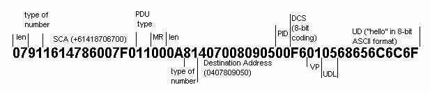
07911614786007F011000A81407008090500F6010568656C6C6F this is the PDU stored in location 2
OK
at+cmss=2 send the message stored in location 2
+CMSS: 3
OK
at+cmss=2,“0407485455“,129
send the message stored in location 2 to the national (129 = 81H) destination
address „0407485455“
at+cmss=2,“+61419877302“,145 send the message stored in location 2 to the international (145 = 91H) destination address „+61419877302“
at+cpms? are messages stored on the SIM-Card?
+CPMS: "SM" , 3 , 7 , "SM" , 3 , 7 on this SIM-Card are 3 message stored
OK you can store at most 7 messages
at+cmgr=3 read stored message in location 3
+CMGR: 0,,24
07911614786007F0040B911604994743F400009930139100406B05E8329BFD06 This is a PDU (SMS-
OK -DELIVER) sent by the
Service Centre
Appendix
Appendix A - Default Alphabet
| b7 | 0 | 0 | 0 | 0 | 1 | 1 | 1 | 1 | ||||
| b6 | 0 | 0 | 1 | 1 | 0 | 0 | 1 | 1 | ||||
| b5 | 0 | 1 | 0 | 2 | 0 | 1 | 0 | 1 | ||||
| b4 | b3 | b2 | b1 | 0 | 1 | 2 | 3 | 4 | 5 | 6 | 7 | |
| 0 | 0 | 0 | 0 | 0 | @ | SP | 0 | P | p | |||
| 0 | 0 | 0 | 1 | 1 | ! | 1 | A | Q | A | q | ||
| 0 | 0 | 1 | 0 | 2 | $ | 2 | B | R | B | r | ||
| 0 | 0 | 1 | 1 | 3 | 3 | C | S | C | s | |||
| 0 | 1 | 0 | 0 | 4 | 4 | D | T | D | t | |||
| 0 | 1 | 0 | 1 | 5 | % | 5 | E | U | E | u | ||
| 0 | 1 | 1 | 0 | 6 | & | 6 | F | V | F | v | ||
| 0 | 1 | 1 | 1 | 7 | ‘ | 7 | G | W | G | w | ||
| 1 | 0 | 0 | 0 | 8 | ( | 8 | H | X | H | x | ||
| 1 | 0 | 0 | 1 | 9 | ) | 9 | I | Y | I | y | ||
| 1 | 0 | 1 | 0 | 10 | LF | * | : | J | Z | J | z | |
| 1 | 0 | 1 | 1 | 11 | + | ; | K | Ä | K | ä | ||
| 1 | 1 | 0 | 0 | 12 | , | < | L | Ö | L | ö | ||
| 1 | 1 | 0 | 1 | 13 | CR | - | = | M | M | |||
| 1 | 1 | 1 | 0 | 14 | ß | . | > | N | Ü | N | ü | |
| 1 | 1 | 1 | 1 | 15 | / | ? | O | O |
abbreviations:
- MS - Mobile Station
- SME - Short Message Entity
- SMSC - Short Message Service Centre
- MMI Man - Machine Interface
- PDUs - Protocol Data Units
- SM-AL - Short Message Aplication Layer
- SM-TL - Short Message Transport Layer
- SM-RL - Short Message Relay Layer
- SM-LL - Short Message Link Layer
- PDU - Type Protocol Data Unit Type
- MR - Message Reference
- OA - Originator Address
- DA - Destination Address
- PID - Protocol Identifier
- DCS - Data Coding Scheme
- SCTS - Service Centre Time Stamp
- VP - Validity Period
- UDL - User Data Length
- UD - User Data
- RP - Reply Path
- UDHI - User Data Header Indicator
- SRI - Status Report Indication
- SRR - Status Report Request
- VPF - Validity Period Format
- MMS - More Messages to Send
- RD - Reject Duplicate
- MTI - Message Type Indicator
- ME - Mobile Equipment
- TE - Terminal Equipment
- SIM - Subscriber Identity Modul
error codes:
- 0 - phone failure
- 1 - no connection to phone
- 2 - Phone-adaptor link reserved
- 3 - operation not allowed
- 4 - operation not supported
- 5 - PH-SIM PIN necessary
- 10 - SIM not inserted
- 11 - SIM PIN required
- 12 - SIM PUK required
- 13 - SIM failure
- 14 - SIM busy
- 15 - SIM wrong
- 16 - incorrect password
- 20 - memory full
- 21 - invalid index
- 22 - not found
- 23 - memory failure
- 24 - text string too long (+CPBW)
- 25 - invalid characters in text string
- 26 - dial string to long
- 27 - invalid characters in dial string
- 30 - no network service
- 31 - network timeout
- 100 - unknown
- 265 - PUK for theft protection necessary
- 266 - PUK2 for SIM necessary
267 PIN2 for SIM necessary
Appendix B- SMS set up for the M20 Terminal
This document describes the process of sending SMS messages between a mobile phone and the M20 Terminal. The mobile phone referred to in this document is the Ericsson GH688. However, SMS message can be sent out or received in a similar fashion using other mobile phones.
Hardware Requirements
The following items are needed.
1. A mobile phone that is capable of sending and receiving SMS messages
2. A M20 Terminal
3. Two SIM cards (one for the mobile phone and the other for the M20 Terminal)
4. A GSM antenna
5. A power cable for the M20 Terminal
6. A RS-232 cable
7. A PC running on Windows Terminal, HyperTerminal or equivalent.
Hardware Set Up
1. Mobile Phone Set Up
Insert a SIM card into the mobile phone and turn the phone on. The phone is now ready for sending and receiving SMS. Note that you need the phone number for SMS messages.
2. M20 Terminal Set Up
Connect the M20 Terminal to a PC as shown in Figure 1. Then do the following:
1. Turn on the PC and run Windows Terminal, or HyperTerminal.
2. Connect the M20 Terminal to COM1 or COM2 of the PC.
3. Insert a SIM card into the M20 Terminal and turn the M20 Terminal on.
4. In Windows Terminal, select [Communications] from [Settings] and set the M20 Terminal to the parameters in Table 1.
Table 1: Communications Settings
|
Baud Rate |
19200 bps |
|
Data Bits |
8 |
|
Stop Bits |
1 |
|
Parity |
None |
|
Flow Control |
Hardware |
|
Connector |
COM1 or COM2 |
5. Reset the M20 Terminal to factory default using AT&F, and hence configure the M20 Terminal for SMS using the following AT commands.
a) AT+CMGF=0[ENTER] [2]
Set the M20 Terminal to PDU mode
AT+CMGF=1[ENTER]
Set the M20 Terminal to text mode[3]
b)AT+CSCA=”+61418706700”[ENTER] Enter the SMS Centre Address
Note that the Service Centre Address only needs to be entered once for all SMS.

Figure 1: M20 Terminal Set Up
Sending a SMS Message
1) Phone initiated SMS Message
A mobile phone that is capable of sending and receiving SMS messages can be used to send a SMS message to the M20 Terminal. Note that the SIM card for the mobile phone must be on the same network as the SIM card in the M20 Terminal for SMS messages. eg. both SIM cards must be Telstra, or Optus.
To send a SMS message to the M20 Terminal, select [Send Messages] from the [Mail] menu and then select [New]. Enter your text and when you have finished press the “YES” button. You will then need to enter the destination number for the SMS message. This is the phone number on the SIM card used by the M20 Terminal[4].
2) M20 Terminal initiated SMS Message
a) Send a PDU SMS
In PDU mode, to send a message like the word “hello”, initially, you have to convert it to a PDU format message. Refer to section 3 (Parameter description) for details on how to construct the PDU message. Note that the actual length of the PDU string (without the Service Centre Address) must be specified for all SMS. Follow the steps below for sending the SMS message.
Step 1. Enter the actual length of the SMS message in octets[5]
AT+CMGS=18[6]
Step 2. Enter the SMS message in PDU format and terminate it with “CTRL Z”
>0011000A81409178699100000105E8329BFD06[CTRL Z]
The M20 Terminal should return
+CMGS: 12
where 12 is the message reference MR, which is different for every SMS message sent.
b) Send a text SMS
In text mode, to send a message, eg. “hello”, follow the three steps below.
Step 1: Set the M20 Terminal for text SMS using
AT+CMGF=1[ENTER]
Step 2: Enter the destination phone number in international format[7]
AT+CMGS=”+61419879619”[ENTER]
Step 3: Enter the text message and terminate it with “CTRL Z”
>hello[CTRL Z]
The M20 Terminal should return
  +CMGS: 1
  OK
where 1 is the message reference MR, which is different for every SMS message sent.
Receiving/Reading/Deleting a SMS Message
1) Mobile Phone
When there is a new SMS message arrived, the phone will beep and the SMS message indicator will appear on the phone screen.
To read the SMS message, select [Read Messages] from the [Mail] menu using the left or right arrow button and the new message is usually shown first. Press the “YES” button
to read the message. The message can be deleted using the “CLR” button.
2) M20 Terminal
a)Read a PDU SMS
In PDU mode, when the M20 Terminal receives a SMS message, the following message will appear on the PC screen.
+CMTI: “SM”, 1
where 1 is the memory location in which the message can be read from.
To read a SMS message from a particular location in memory (eg. location 1) use the AT+CGMR command as follow.
AT+CMGR=1[ENTER]
The M20 Terminal should return the PDU message as follow.
    +CMGR:
    0,,24
    07911614786007F0040B911604994743F400009930139100406B05E8329BFD06
       OK
where 0 is the status code indicating a received and already read message, 24 is the hexadecimal number indicating the length of the message.
b) Read a text SMS
Like PDU mode, when the M20 Terminal receives a SMS message, the following message will appear on the PC screen.
+CMTI: “SM”, 1
where 1 is the memory location in which the message can be read from.
To read the SMS message use the AT+CGMR command as follow.
AT+CMGR=1[ENTER]
The M20 Terminal should return the text message as follow.
    +CMGR: “REC READ”,“+61407809050”,“98/12/01,20:16:11+44”
    hello
    OK
c) Delete a SMS message
The SMS message can be deleted from memory (eg. location 1) using the AT+CMGD command as follow. Note that there is no AT command to delete all the SMS messages at once.
AT+CMGD=1[ENTER]
The M20 Terminal should return OK.